8 bits shift register - 17 bits of data
Although the serial-in, parallel-out shift register, aka. SN74AHC595, SN74AHC594 or just "595" / "594", is an easy component to hook up and use, it might not be immediately obvious what's going on inside the chip. At least it was not to me. Therefore I found Mike Szczys's demonstration very enlightening. He shows how to drive the shift register manually, all without any micro-controller. The functional pins of the register is hooked up to buttons, so he can slowly go through the sequence of setting the data bit, clocking or shifting that onto the register, and then closing the latch to show the result on a line of LEDs.
Combined with the data sheet for the 595, it becomes more clear how the chip works: There are two separate registers on the chip; the visible storage register, and the internal shift register. When the latch (aka. "RCLK", or "ST_CP") goes high, the bits from the shift register is copied over to the storage register, and becomes visible on the external pins.
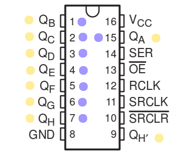
So that makes for 16 potentially different bits of information. However, as the title suggest, there's one more available: It's the output pin, typically used to daisy chain multiple shift register chips together. Even though it is part of the internal shift register, which thus consists of 9 bits, it is externally visible, and retains its state after the latch is closed. The drawing below shows this, with nine yellow external dots indicating visible bits, and eight blue dots indicating internal bits, for a total of 17 bits.
In the figure I've marked the QH' as externally visible, even though it is part of the internal shift register. There probably aren't many applications in which you'd use that as an active output, but one that comes to mind is a 3x3x3 LED cube. In a typical setup, you'd have three layers of 9 LEDs, for 12 wires altogether. Instead of controlling each LED in a layer individually, you could use a shift register, however you'd be one pin short (or 7 pins wasted if using two chips). So why not use the output pin for the 9th LED?
The programming would work as normally when addressing a shift register, but instead of shifting out 8 bits, you'd shift 9. The only problem would be that the 9th LED connected to the output pin would see the previous bits flying past as new bits are shifted onto the register. This might not be a big problem, as cycling the layers will probably be too fast to notice. If it is an issue, one could just disable all layers while bits are shifted out, and turn on only the relevant layer when done. I think this is a small experiment I'll have to make, so stay tuned.
