Simple multiplexing with two shift registers
There are many ways to drive multiple LEDs, which in sum would require more IO pins and more current than is available on the control chip. The simplest way is perhaps multiplexing, and in this example I've used two 8 bits serial-in/parallel-out shift registers to achieve that. I'll skip the theory for now, but I think the structure and layout of the LED matrix is worth highlighting.
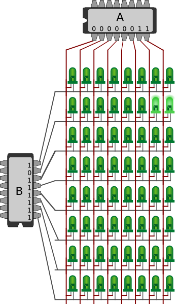
Below the 64 LEDs are shown in a grid of 8 columns and 8 rows. To light a specific LED, there has to be a potential difference between its two pins, thus the pin connected to a column should be set HIGH, and the other row pin to LOW. To individually control all the LEDs, the active row is cycled very quickly. For each step of the cycle, the specific LEDs of that row is set, and then changed for the next row. If done quickly enough (typically at least 50 times per second; 50 Hz), it will appear as if all the LEDs are always on.
The example in the figure shows register A set to 0000 0011, for the two right-most LEDs. Register B is set to 1011 1111, thus activating the second row from the top. In theory, the settings of the two registers could have been reversed, and then the two bottom LEDs of the second column had been lit. However, since LEDs are directional, and does not let current through when the polarity is reversed, this is not possible (at least not with the simple diagram shown below).
Please note that the drawing glosses over a few details: First, the pin-placements of the chips are not as per specification; the right most pin, in case of register A and top for B, are in fact ground. Pin 0, for the first bit of the register is actually on the opposite side (which is always rather annoying and confusing). See this post for details.. Secondly, there should be an array of resistors: one between each column line and chip A (see this picture as an example). Finally, although it is possible to drive the LEDs from the Arduino, as seen in the pictures further down, external power will improve brightness, thus a set of resistors would also be required.
Once the LED side of the registers are hooked up, there are a few wires to connect to the Arudino: Each shift register needs at least its data-in, clock and latch pins connected (plus pins which need high or ground). The data pin sets the next bit to be pushed onto the register. The clock pin does one shift on its transition to HIGH. Finally, the latch pin copies the content of the internal shift register onto the externally visible storage register. See Mike Szczys’s video for details on how this works.
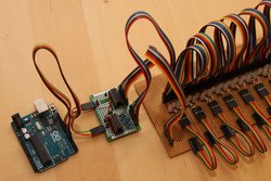
There are a few ways these three wires from each register can be hooked up. One way, as seen in the pictures and code below, is to connect each data, clock, and latch pin separately, for a total of six IO pins on the Arduino. It is also possible to sync the latch of both registers, thus combining both of these pins onto a single IO pin. The code below could have benefited from this optimization (see the comments in the code). Secondly, it is possible to sync both latch and clock pins of both registers, and shift out two bits in parallel. In code, this would thus only required a single for-loop, however, an extra call to digitalWrite() (for the second data bit) would be required. I've not measured what difference this makes, so any insight here is welcome. Finally, it would be possible to daisy chain the two shift registers together. This would only require three IO pins, however would waste a lot of time shifting redundant bits onto the second shift register.
// Code under GPL; please see full file for details.

// Digital pins for two independent shift registers.
const int dataA =  5;
const int latchA = 6;
const int clockA = 7;

const int dataB =  8;
const int latchB = 9;
const int clockB = 10;

const int outputPinCount = 6;
const int outputPins[outputPinCount] = {
  dataA, clockA, latchA, dataB, clockB, latchB};

// Frame buffer
const int lights = 64;
int buf[lights];

void setupPins() {
  for (int i = 0; i < outputPinCount; i++) {
    pinMode(outputPins[i], OUTPUT);
  }
  clearAll();
}

void setup() {
  Serial.begin(9600);
  Serial.println("reset");

  setupPins();
  setAll(1);
}

void loop() {
  display();
}

void clearAll() {
  setAll(0);
}

void setAll(int v) {
  for (int i = 0; i < lights; i++) {
    buf[i] = v;
  }
}

void display() {
  for(int grp = 0; grp < 8; grp++) {
    digitalWrite(latchB, LOW);

    // Writes a single bit to the B register.
    // 0 means that group is active / on, 1 means off.
    // At the beginning of the loop, one 0 is shifted
    // onto the first bit, and later shifted upwards
    // as 1s turn the previous groups off.
    digitalWrite(clockB, LOW);
    digitalWrite(dataB, grp == 0 ? 0 : 1);
    digitalWrite(clockB, HIGH);
    digitalWrite(latchA, LOW);

    // Depending on the arrangement of the LEDs, and which
    // bits are conceptually most/least significant, shift in
    // increasing or reverse order.
    for(int i = 7; i > -1; i--) {
      digitalWrite(clockA, LOW);

      int bit = buf[grp * 8 + i];
      digitalWrite(dataA, bit);

      digitalWrite(clockA, HIGH);
    }

    // Here and above, both latches are set to the same
    // value at the same time, this could have been combined
    // onto the same IO pin.
    digitalWrite(latchA, HIGH);
    digitalWrite(latchB, HIGH);
  }
}
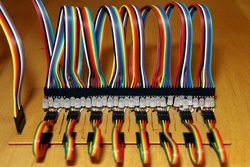
In the pictures below, the LEDs are on a single line, rather than in a grid, however, the grouping seen above still applies. Furthermore, each LED in my project is dual colour, so there only 32 of them, but still 64 pins to control. On my LED "breakout board" I've added a double set of headers for each pin on each LED, so I can easily connect them in any combination. The 8 pin jumper-wires from this post really came in handy.
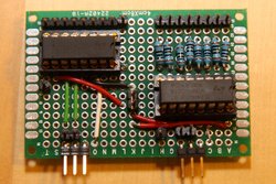
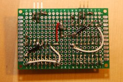
For my custom dual shift register breakout board, I used this 4 x 6 cm PCB, and made the pins I needed available through headers. Please note that I made a mistake when placing the output headers, and for some reason assumed the pin on the opposite side was Q8 or QH, rather than 0 / A. On the shift register without resistors, I was able to correct this because there was room, however the other one was flush with the side, so it had to be corrected in the wiring (which makes some of the pictures below misleading). This board is somewhat similar to what you can buy pre-made from DealExtrme, however their version is using two daisy chained shift registers, and as mentioned, this will waste time when cycling the groups of LEDs.
Finally, note again that although it is possible to drive all this from the Arduino, even when powered over USB, better performance will be achieved with a higher powered external brick. Also, note that it is possible to mess up the code, so that all LEDs are turned on at the same time, and potentially draws more than 1 A. I shall not be held liable for what ever damage that might cause to hardware or people. Please see the license in the code for details.
First, some "making of" pictures, soldering all the LED pins and headers.
And here's the final product, well at least for now.
