Wifi with the ESP8266
The ESP8266 is an interesting chip that has gained a lot of traction lately. At only $5, it's quite impressive what you get: a wifi to serial adapter, a TCP/IP stack, and even an embedded user-programmable micro controller. It is in fact a complete System-on-a-Chip itself. As an adapter, it can easily be connected to a micro controller like the Arduino, and there is now also an SDK to program it stand-alone. Espressif, the Chinese company behind it targets the "Internet of Things" market, which is bound to grow in the near future. They also seem keen on creating an open source community around the chip, with an open source Github project, the open source SDK, and a community forum.
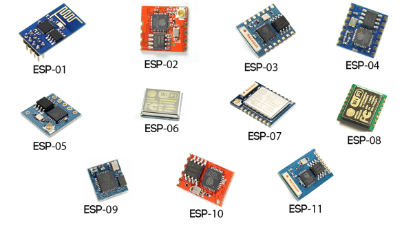
The chip comes on a large range of modules and break-out boards, as seen below. Deal Extreme stocks most of them, and I got the ESP-01 with easy to use header pins.
With a bit of help from various blogs about the board, I had it up and running. The basics are neatly explained by ray, with the AT commands to try out first. shin-ajaran goes into a bit more detail about the wiring and other options. And once you have it running, the MIT class instruction mentions a few scripts to try out. Finally, Dave Vandenbout explains firmware flashing and more advanced use.
My own Hello World attempt does not add much to what is already mentioned above. To summarize, my basic setup includes:
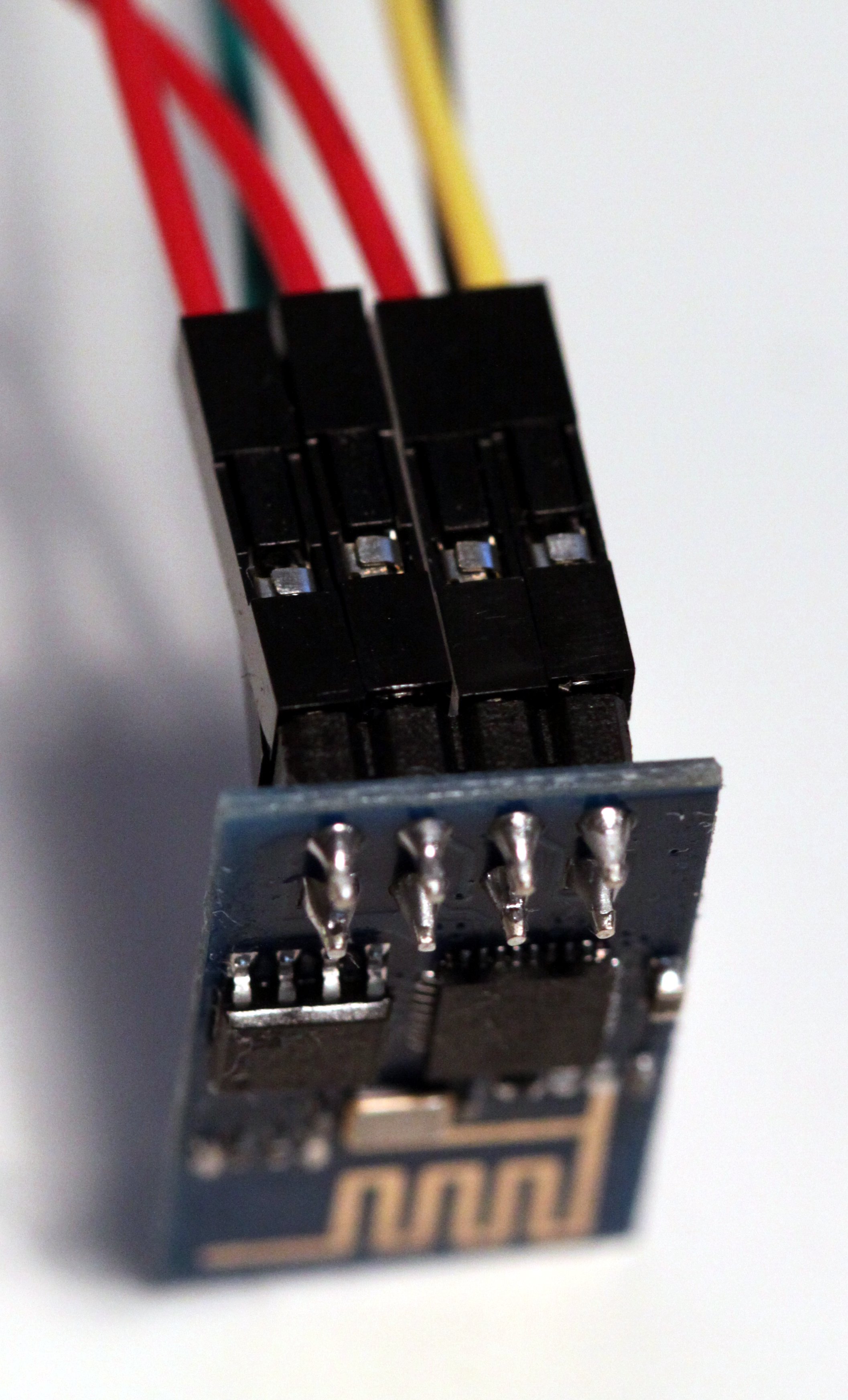
- The ESP-01 ESP8266 board.
- A USB-to-TTL serial cable, e.g. based on the PL2303
- Assuming you get a 5V USB-TTL cable, you need to lower the input voltage. I got the $2 AMS1117 Power Module
- Two resistors for a 5 to 3.3 voltage divider. I went with 100 and 220 Ohm; see shin-ajaran blog post for details.
- A breadboard to connect the voltage divider.
- Also note, I had to connect both the reset (RST) pin and CH_PD pin to 3.3 VCC before the terminal on the computer connected.
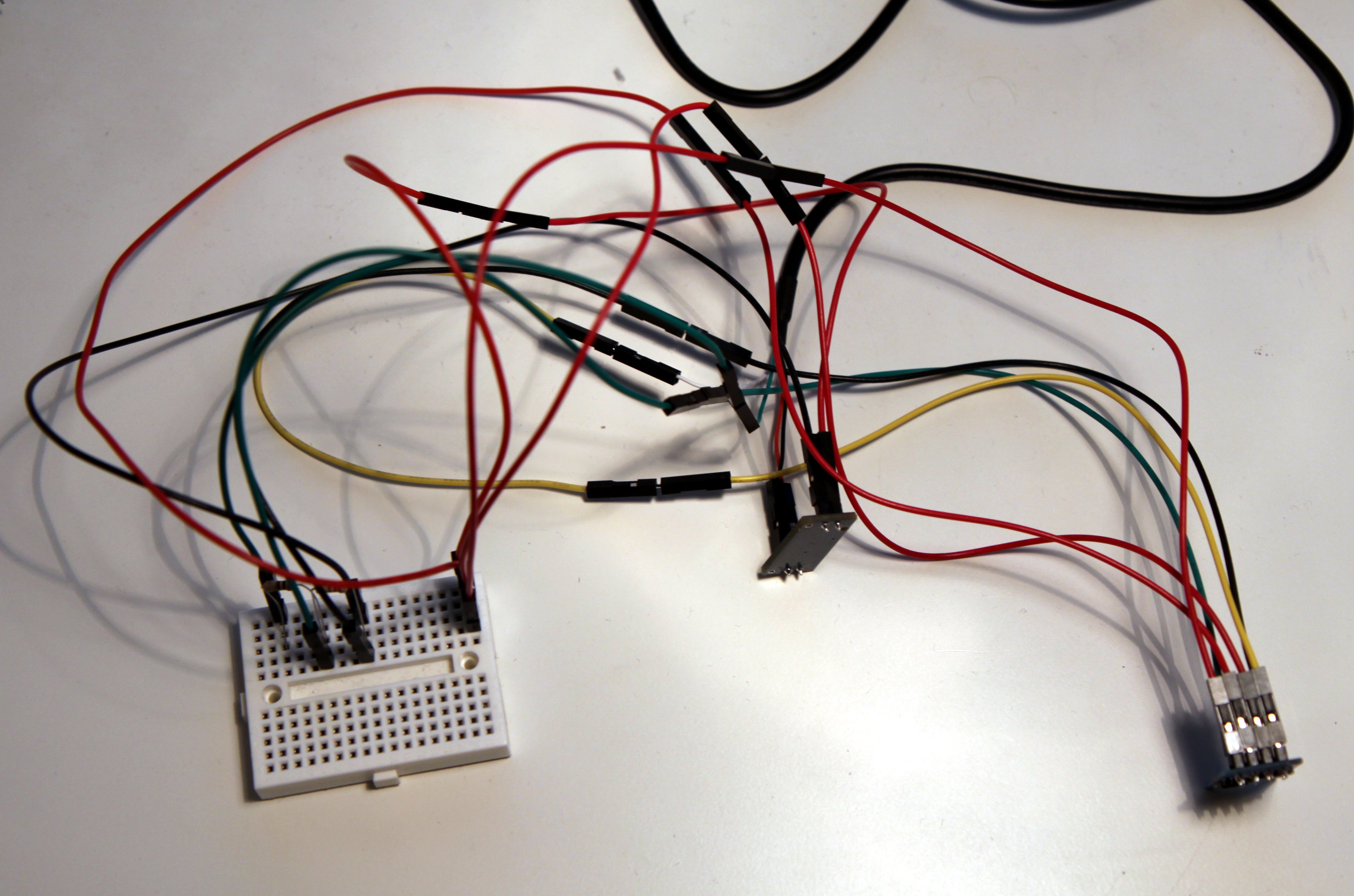
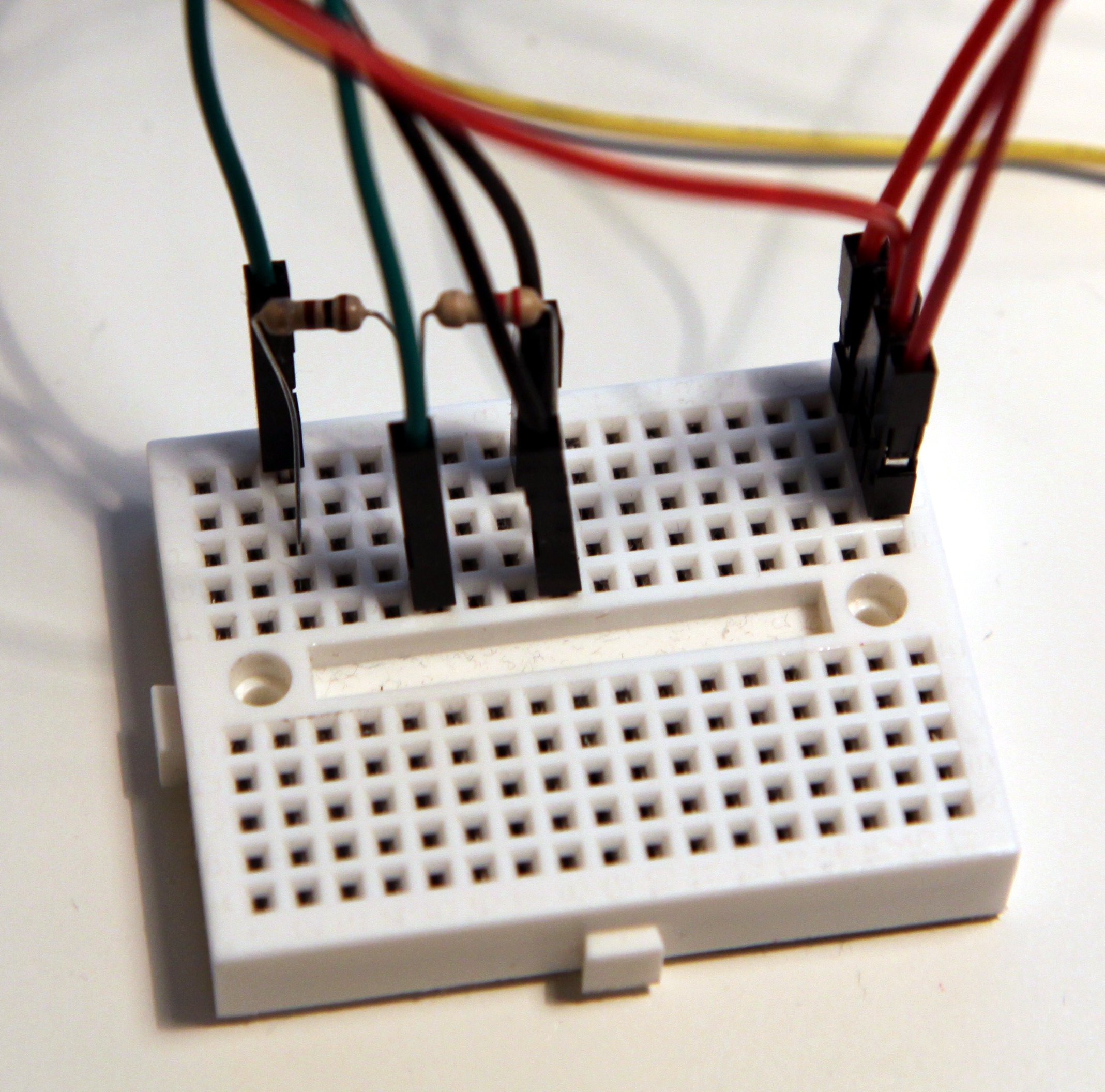
In the pictures below I've tried to show my setup. Not sure how much clarity it adds, though. It shows the pins of the esp-01: red for 3.3 VCC, black for ground, green for URXD (connected via a voltage divider, and matching green on the PL2303 cable), and yellow for UTXD (connect directly to white on the PL2303 cable). The breadboard shows the voltage divider, and all the red VCC wires connect (but of course not connect to the resistors).