3x3x3 LED cube with fewer wires
A few weeks ago, I mentioned that it would be possible to optimize the number of wires and components needed for a 3x3x3 single colour LED cube by using "the 9th bit" (the output pin, intended for daisy chaining) on a 8 bit serial in / parallel out shift register. Other examples of the 33 cube I've seen are simply pulling 12 wires (9 LEDs on each layer, and 3 layers) back to the Arudino. At that scale, it is of course feasible, but still, when it's possible to get by with half, why not? So I put together a small 33 cube doing just that.
Previously, I made the claim that the 8 bit shift register retains 17 bits of data. I'll have to revise that down, to 16.5 bit. It is possible, as already mentioned, to use the output pin as a 9th visible output, as seen in the images and code below. However, the value of the output pin is shared with the 8th element of internal register, thus 17 distinct bits are not realised. It becomes more clear when considering the timing diagram of the of 595. Below is an extract and cut-out from the Texas Instruments data sheet [PDF].

The diagram above is truncated both in the horizontal and vertical axis, to highlight the last cycles, when the output pin, denoted QH' in the digram, gets its value. As can be seen, when the 7th pin, or QG, is shifted up one (the first red line, when RCLK goes from high to low), QH' gets that bit set as well. Note that the internal states of the shift register is not shown here. In the next cycle, SRCLK is latched, and the internal value of the 8th pin is made visible on QH, on the yellow line. The result is, that either QG + QH' are on at the same time, or QH + QH'. This was frustratingly easy to reproduce in code, but not what I wanted.
To control all the nine LEDs of a layer independently, I had to set the output pin after the other eight pins were latched. However, if cycling quickly, it would then not get enough time on, and thus would look very dim. The final trick was to insert a short delay after all pins were set correctly, as seen in the code and discussion on timing below.
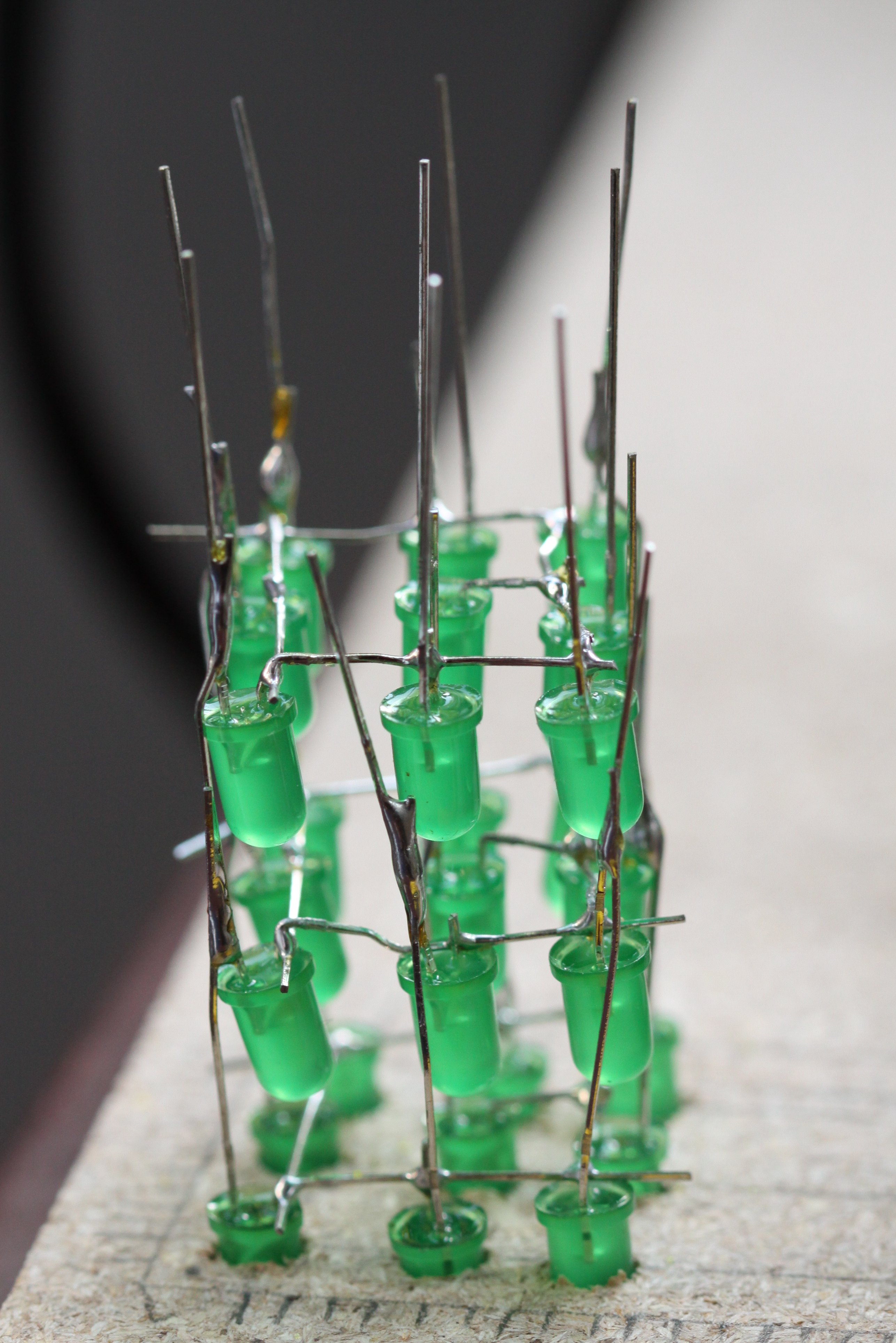
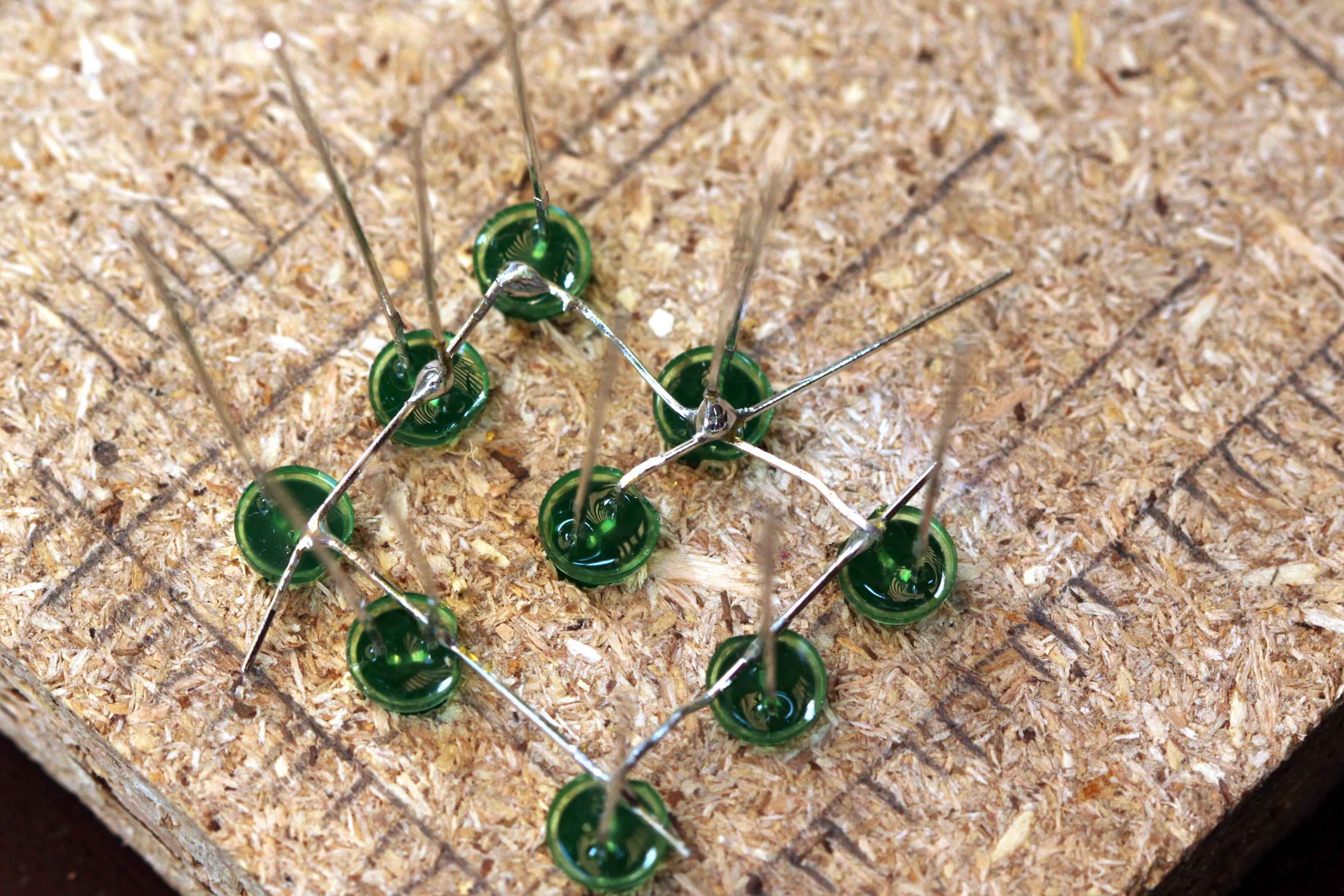
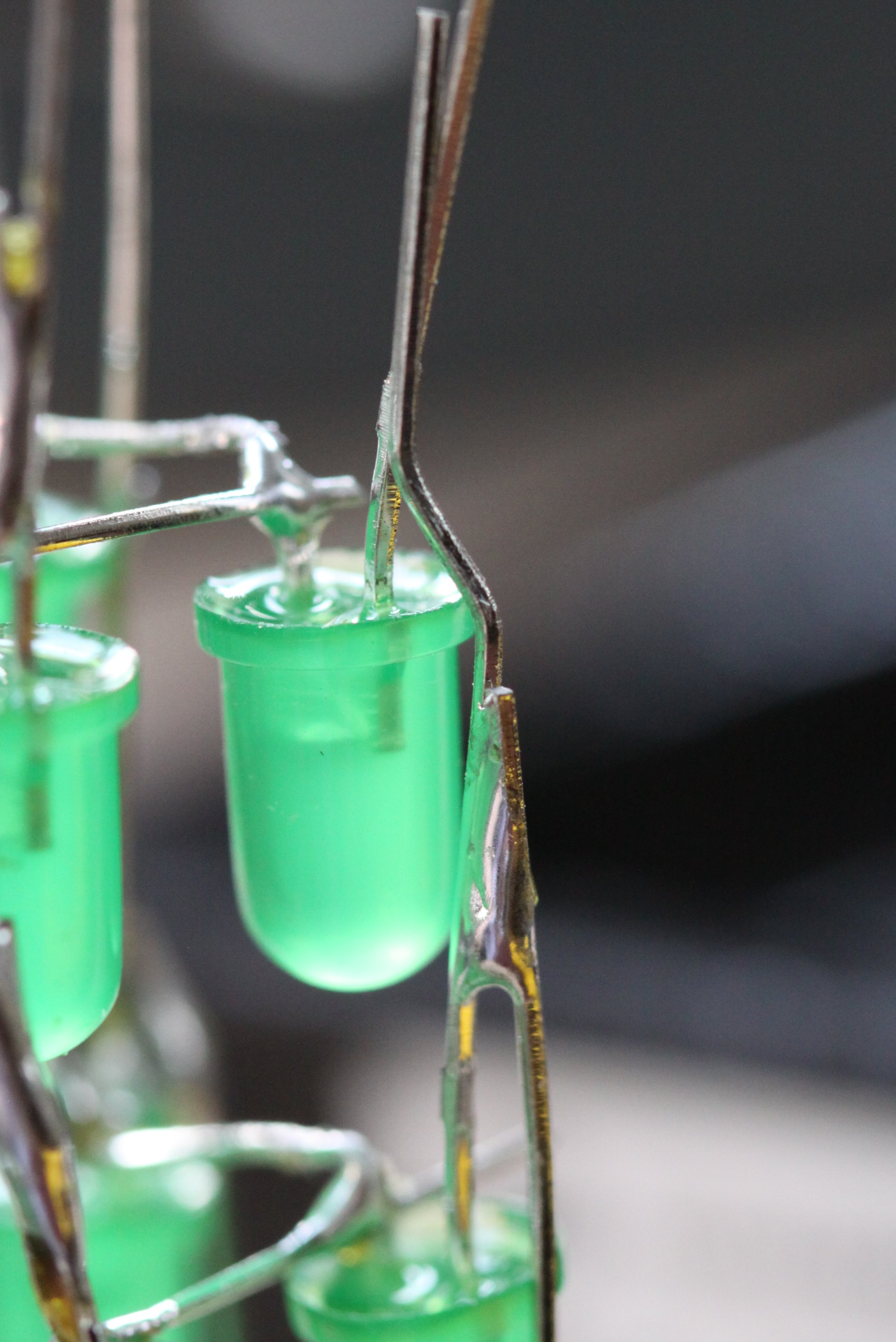
For the construction of the cube, I used LEDs from a 100-pack for $4.30 from DealExtreme, soldered onto a small 4x6cm (14x20 points) PCB. Following “fruitkid101″ video instructions, I drilled holes for a template in a piece of wood. As it was all by hand, it turned out a bit skewed, but for this small project I found it didn't matter so much. Next time I'll be a bit more precise. Soldering the legs together turned out be easy. I made the spacing between the LEDs small enough for one cathode leg to reach across its two neighbours, which meant that I only had to bend the ones in the corner. I soldered the corners first, and then the ones in between, finishing off with the centre LED. Positioning the anode legs between the layers was a bit more tricky, but with a double bend, as seen in the picture below, it was easy to make the leg from the layer beneath stay close enough to solder to its upstairs neighbour. Since the joints were for both the electrical contact, as well as the structural, I applied quite a bit of solder.
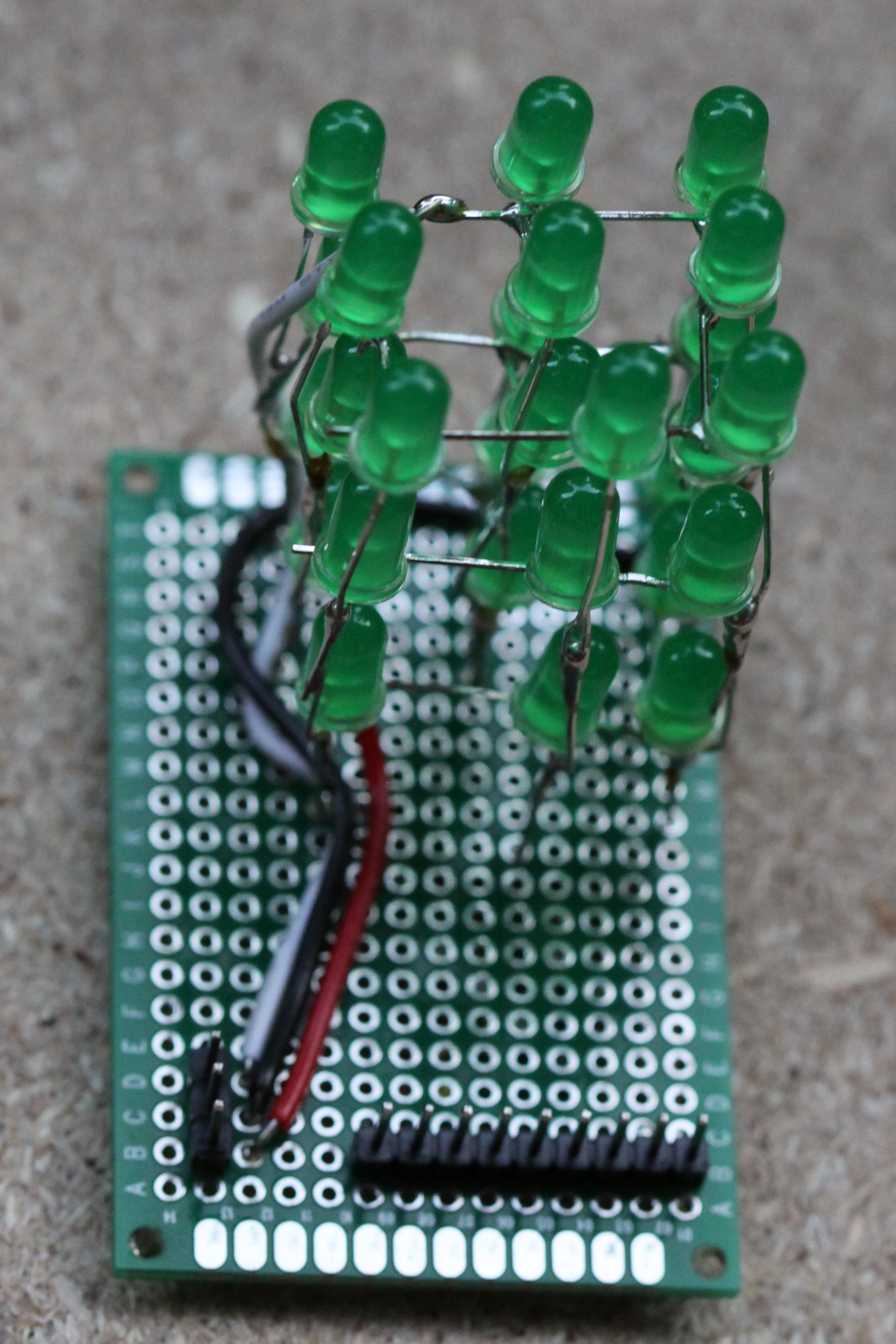
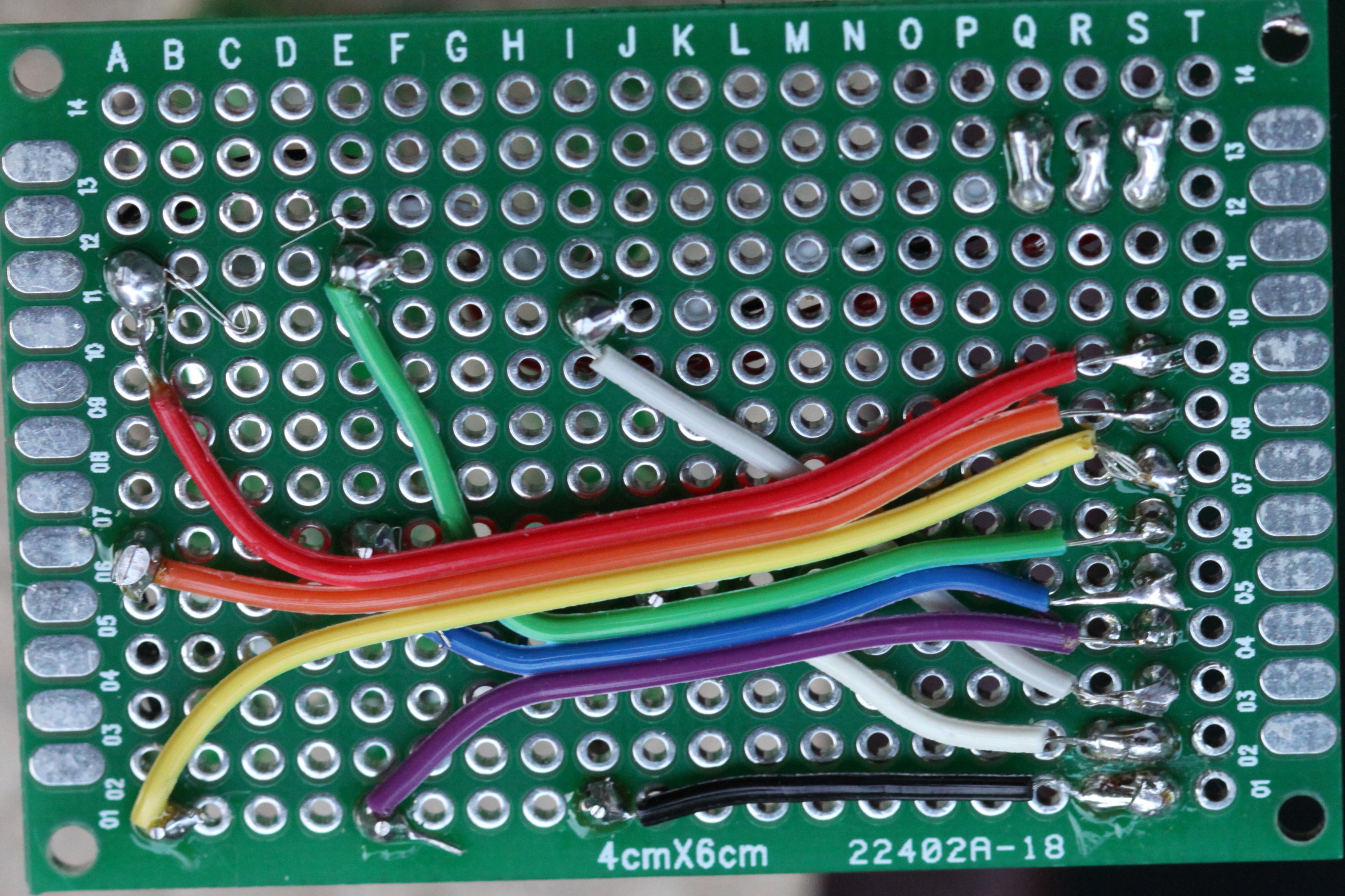
The interface to the Arduino is through the three direct pins which controls the sinks for each layer, and three pins for data, clock and latch of the shift register. The overview can be seen in this picture, and below. The small breadboard with the shift register also contains a 100 Ohm resistor for each pin, including the output pin.
  |
 |
As mentioned above, part of the motivation for this project was to control the cube with fewer pins, and use the output pin of a shift register for the 9th LED. That led to another interesting revelation in the code, and how to control brightness. As seen in the snippet below, which includes the display() method and the external fields used, the first inner for-loop for the shift register is all normal. It shifts the first 8 bits, with Most Significant Bit in the 8th element (index 7) of the display buffer buf[]. Surrounding that for-loop is the latch, however, notice that on the first line of the outer for-loop, the layer pin is set HIGH, which means, it is turned off. Before the layer we operate is turned on, the output pin is set to the value of buf[8] (and equivalent for higher layers). This is done within the second inner for-loop, inside the if-block. Strictly speaking, the if was not necessary; it would have been fine to shift out the extra bits every time.
Only after every pin is set to its correct state, is the layer turned on and the LEDs lit. However, if doing this without a delay, the LEDs would seem very dim, or almost off. Even if running the display() method only takes 400 micro seconds without the delay, for a good 2500 iterations per seconds, the problem would be that the LEDs would be turned off most of the time. To fix that, the delay is inserted, which holds the LEDs for a little while per iteration over a layer. With a one millisecond delay, the full method takes 3.4 ms, and can be executed ~300 times per second or a 300 Hz refresh rate of full cube.
However, with a delay of only 1 millisecond the LEDs are still somewhat dim. The fraction of time where the LEDs are off is still significant: For each layer 400/3 = 133 µs off vs. 1000 µs on, or about 12% of the time. If the delay is increased to 2 milliseconds, that ratio goes down to 6%, and the LEDs are noticeable brighter. The refresh rate goes down to ~150 Hz, but we are still far from the 50 Hz limit which is required to avoid flickering. In fact, we can go all the way up to a 6 ms delay before the limit is near (1000 ms / 50 / 3 = ~6 ms). However, it is hard to notice a difference between 3 and 6 ms delay. It would have to be measured. The lesson learnt then, is that it is not the refresh rate which matters the most when multiplexing LEDs, but rather the ratio of time the LEDs are on. Furthermore, with a 16 MHz MCU like the ATmega328, there is plenty of room for doing other stuff, and little need for premature optimization of code.
Future work will include utilizing the Arduino timer library for controlling the display buffer. Currently, that bit of the code is rather clunky. I would also like to experiment with fading and controlled blinking. Again, the timer library will be useful, but I'd probably also use the buffer to hold an intensity value, rather than just on/off. Also, I would like to measure the brightness with the different delays discussed above. One way would be using an LDR (light dependent resistor), but I might also look at the cheap $30 lux meters from DealExtreme. Finally, I'll of course have to make some interesting patterns and animations, which should lead to an API for some level of abstraction. There's lots to do!
Extract from code. See the full file for further details and GPL 3 license.

// Digital output pins

const int data =  5;
const int latch = 6;
const int clock = 7;

const int layer0 =  9;
const int layer1 = 10;
const int layer2 = 11;

const int layers[3] = {layer0, layer1, layer2};

const int outputPinCount = 6;
int outputPins[outputPinCount] = {
  data, clock, latch, layer0, layer1, layer2};

// Frame buffer
const int lights = 27;
int buf[lights];


void display() {
  for(int l = 0; l < 3; l++) {
    // Turns the layer off
    digitalWrite(layers[l], HIGH);

    // Shifts out the first 8 bits
    digitalWrite(latch, LOW);
    for(int i = 0; i <= 7; i++) {
      digitalWrite(clock, LOW);
      int bit = buf[l*9 + 7-i];
      digitalWrite(data, bit);
      digitalWrite(clock, HIGH);
    }
    digitalWrite(latch, HIGH);

    // Shifts 9 more bits to set the output pin
    if (buf[l*9 + 7] != buf[l*9 + 8]) {
      digitalWrite(data, buf[l*9 + 8]);
      for(int i = 0; i <= 8; i++) {
	digitalWrite(clock, LOW);
	digitalWrite(clock, HIGH);
      }
    }

    // Turns the layer on, and hold for 3 ms
    digitalWrite(layers[l], LOW);
    delay(3);
    // Turns the layer off again
    digitalWrite(layers[l], HIGH);
  }
}